Waste Injection Pump Skid Despatched
An offshore, high pressure waste injection pump skid has just been despatched from our factory. All design, build and testing was carried out by Calder and our engineers will be following the unit to site for installation and commissioning. This pump is designed to function in a hazardous area classified as Class 1, Div. 2 (Zone 2) within the challenging environment of offshore waters. To facilitate installation on an existing platform with constrained deck space, the unit is of a modular design. This enables disassembly in Worcester and subsequent reassembly at the installation site. The unit has now been carefully dis-assembled and each module secured in its own packing case.
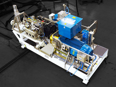
From Design to Despatch and Beyond
Design
There are two significant aspects to the design of this pump skid. First, it has to operate in a Class 1, Div. 2 (Zone 2) hazardous area. Second, the skid will be installed on an existing platform with limited deck space. In both the hazardous area requirement and the modular design, we have vast experience. As with all bespoke projects of this nature, there were weeks of meticulous design work that preceded the start of the build process. Our engineering design team has ensured this unit will operate reliably in the challenging conditions of the North Atlantic Ocean.
Our hazardous area design experience goes back over two decades. The Class 1, Div. 2 (Zone 2) hazardous area regulations used for this unit are similar to those of the European Atex standards. Whilst this unit is compliant with local regulations, it is standard for us to apply Atex rules to achieve a high level of mechanical hazardous area protection for our skid packages. For example, the hoses are anti-static, the packing oil pump drive belt is anti-static, and the mechanical equipment is Atex certified.
To enable the pump skid to reach its final destination on the offshore platform, the skid design is modular. This allows dismantling in Worcester, movement through the platform to the operating location, and rebuilding in situ. We have seen an increased demand over the last ten years for units to be modular. Follow Dan as he leads you through the design and build of a modular, offshore pump skid in this video case study.
Included as part of this project is a DA2 (Design Approach 2) Study. We use Design Approach 2 Studies to model and analyse the acoustics of positive displacement pumping systems and their pipework. This enables us to predict pulsations and vibrations in the system, either confirming that the equipment will operate within accepted parameters, or highlighting issues which we can then address.
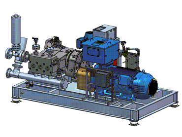
Assembly – Mechanical
The unit was built in bay 1 of our assembly area. Motor and pump first – fitted and aligned. Then the coupling. Following that, it is the ancillary equipment, lubrication systems, flow control devices, pipework, instrumentation and gauges.
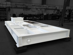
This is when the project really feels like it’s coming alive! The arrival of the baseframe from the paint shop signals the start of the build. This is a fully welded construction painted to offshore specifications. Fitted to the baseframe are anti-vibration mounts which are standard on our units. They protect the deck and the platform by minimising the transference of vibration and noise from the unit.
The frst item fitted to the skid is usually the pump. Most of our well service units utilise triplex reciprocating plunger pumps. This unit has a Duplex stainless steel head to cope with the harsh process fluid. Five-plunger quintuplex pumps are also available. Then follows the motor. In this case the motor is high voltage and suitable for hazardous areas.
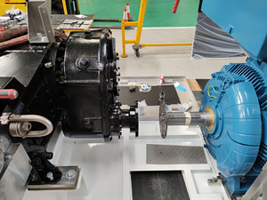
An important part of the pump skid assembly is the alignment of the pump and motor and the fitting of the coupling. Coupling manufacturers recommend maximum tolerances on alignment of rotating equipment. However, we typically work to less than half the recommended tolerance. In order to achieve these greater levels of accuracy, we use the latest laser alignment equipment. This, coupled with the experience our build teams possess, ensures our stringent pump/motor alignment requirements are achieved.
For most of our pump packages, we use shaft-to-shaft couplings. This eliminates the side loads frequently experienced with belt drives. We generally opt for a flexible membrane coupling.
The oil tank for this pump’s lube oil system is integrated into the baseframe. The system includes a lube oil heater due to the low ambient temperature in the operating location. The plate heat exchanger cools the lube oil using seawater. To cope with the seawater, the exchanger is of titanium construction.
Assembly – Electrical
All electrical work is carried out in-house by our team of electrical engineers. Of electrical interest on this unit is the requirement for cabling that meets cold bend and impact testing specifications.
We are frequently complimented by our customers for the quality of our electrical installations. Our Compex-qualified electrical engineers take great pride in ensuring the electrics are not only compliant, but also super precise and neat. Electrical snagging issues are a rarity.
Test
Our customers were here to witness the endurance test of this offshore pump skid. Prior to testing, our customers carried out functional inspections of specific equipment relevant to the pump skid and the test set-up. Then followed the main endurance test lasting four hours. The majority of time was spent in the test bay. However, back in the training room we reviewed the pump skid’s maintenance and operating functions and discussed the on-site installation and commissioning. And we gratefully received F.A.T. sign off with a Code 1 Approved F.A.T. Report.
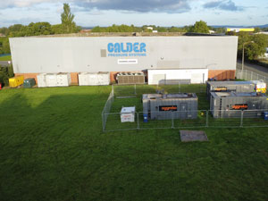
Our test setup is engineered to ensure the highest standards of performance for the units we manufacture. It includes an impressive 1,800 kW Variable Speed Drive (VSD), capable of handling flow rates of up to 250 cubic meters per hour and pressures of up to 4,000 bar. To expand our capabilities and accommodate testing up to 10 kV, we partner with trusted companies who provide us with the HV generators and transformers required to perform our customer-witnessed tests.
This 410 kW unit is among the more powerful units produced by Calder. To achieve the required power levels, we’ve teamed up with Aggreko once again, utilizing their cutting-edge generators and transformers.
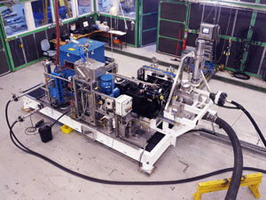
We employ water as our testing fluid which is then recirculated via our test facility heat exchangers and coolers into an atmospheric tank. This approach offers two significant advantages: first, it allows the test water temperature to reduce generated heat and fluid velocity. Second, we proudly embrace water conservation by reusing the same water, minimizing consumption. With a substantial flow rate of 68 cubic meters per hour, we are making a positive impact on water conservation.
Documentation
Given the harsh and remote locations in which these units operate, we have made our name in the industry by focusing on quality. This is applied throughout the whole project. From design through the build, our after-sales support and crucially our documentation and O&M manuals.
Every project has a documentation pack and offshore, hazardous area units are certainly no different. Comprehensive documentation plays a crucial role in demonstrating a pump unit’s compliance with customer and industry standards and regulations. See how important good documentation is to Calder.
Installation and Commissioning
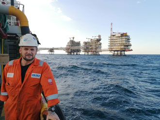
A team of our engineers will follow this pump skid to the offshore platform. There they will re-assemble and commission the unit.
Lifetime Service and Support
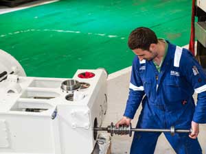
Following successful commissioning we will be here to support our customer for the lifetime of the pump unit. We can offer training, operational spares, and service packages.
Get in Touch
Whatever your application, we are here to help. Please call us on +44 1905 751790 or email sales@calder.co.uk to discuss how we can help you achieve your green energy targets.

